Standard options and upgrades for Lancer X
Electronic stability control system on Lancer X
Installation and activating of electronic stability control system ASC (ESP) with HSA and ESS support on Mitsubishi Lancer X.

Lancer-X.net
Electronic stability control system ASC (ESP) is one of useful options, which, if it is possible, is necessary to install one of the first on Mitsubishi Lancer X, as it a question of your safety.
I have decided to install the modern unit 4670А719 on Lancer X with support of HSA and ESS system. HSA is a hill start assist, and ESS is an emergency stop signal sistem.
For easy reference, this instruction is represented in 2 versions: text and video at the end.
List of components for installation of electronic stability control system on Mitsubishi Lancer X
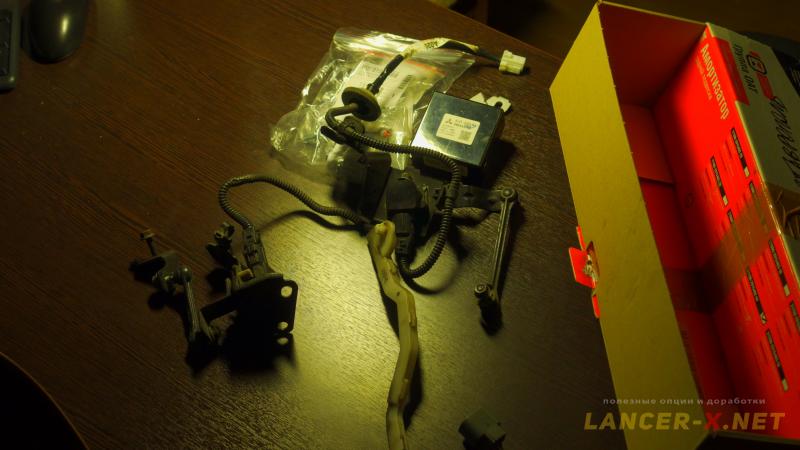
My components for ASC on Lancer X consist of:
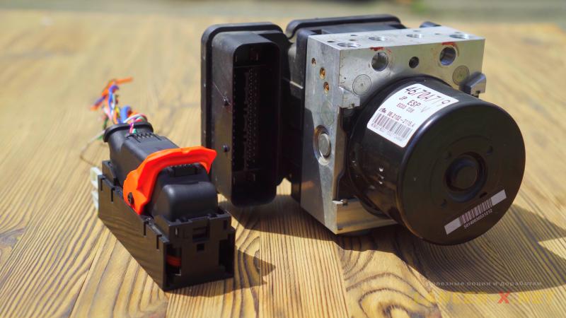 1. ABS/ASC unit - 4670A719.
2. ASC unit bracket - 4670A333 or replica.
3. Three-row connector for 719 unit connection.
4. G-sensor with connector - 4670А148. 149, 282, 730 etc. are also appropriate.
5. G-sensor bracket - 4670A046.
6. Nuts for G-sensor fastening - 2 pcs.
7. Bolts for G-sensor bracket fastening - MF140205
8. Steering wheel position sensor 8651A084 or 086 with connector.
9. Screws of steering wheel position sensor fastening - 3 pcs. - MF456086.
10. ASC OFF 8602A009 or 8602A029 button with connector (for Lancer X from 2011 year of manufacture)
11. Wires of different colors.
12. Clamp bands, adhesive tape, pins.
13. Mortise terminals.
14. Brake fluid.
Connection of ASC OFF button on Mitsubishi Lancer X
If you have Lancer 10 before 2011 year of manufacture (before restyling), then you will have the connector for ASC OFF button connection from the factory, connect button and proceed to the next step.
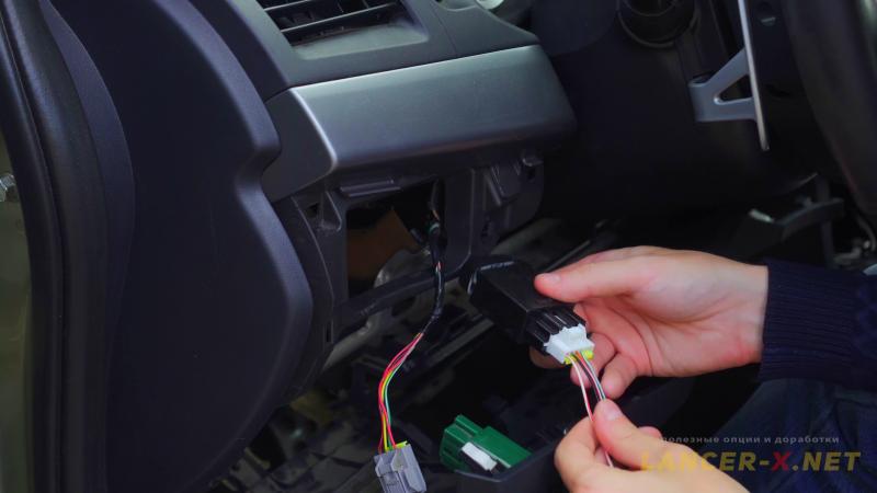
And if you have restyled Lancer 10, like me, then the wiring and connector are absent, one has to restore it. Everything is restored easy enough.
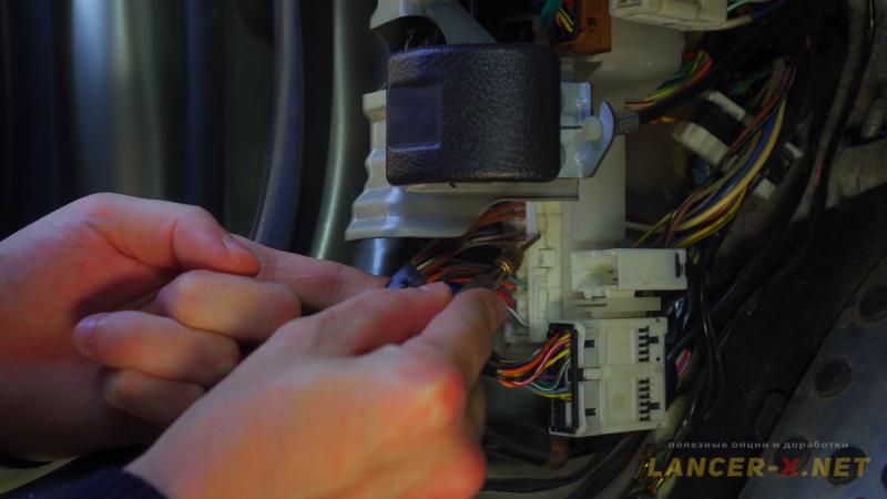
 There are 4 wires for the connection on the connector of electronic stability control system. The wires of 2,3 and 4 buttons of electronic stability control system are necessary to be connected to the same wires by the colors in the manual headlamp levelling device connector.
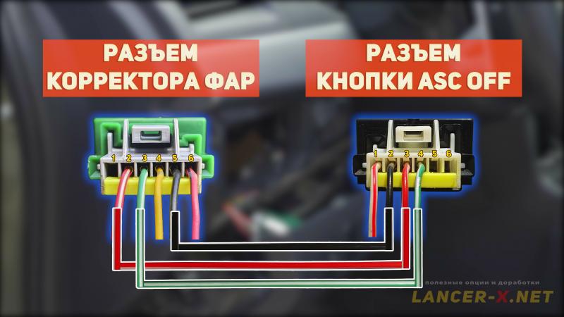 Connect 2 pin with black wire to the 5 pin of manual headlamp levelling device connector.
3 pin with white-red wire to the 2 pin.
4 pin with green-white wire to the 3 pin.
And built-up the 1 pin of connector of electronic stability control system button (1 meter of the wire) and lead it along the standard wiring up to cabin handle of hood opening.
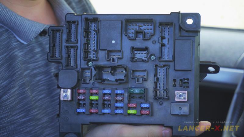
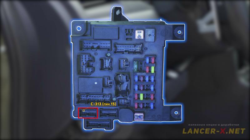 It is necessary to connect 1 pin to the white with red stripe wire, that begins with C 313 pin 15 connector of ETACS unit.
You can immediately cut into this wire, or connect with a mating pin or using a compression terminals in the c-27 pin 5 connector, this connector will be blue and is located near the cabin handle of hood opening. But as I have car of 2011, I had the transient wiring, blue c-27 connector was absent.
 That is why, using a multimeter, I found the necessary wire in this connector, if I'm not mistaken, this is the c-28 connector, we connect to pin 4 using a compression terminal or a mating pin to a white with a red stripe wire.
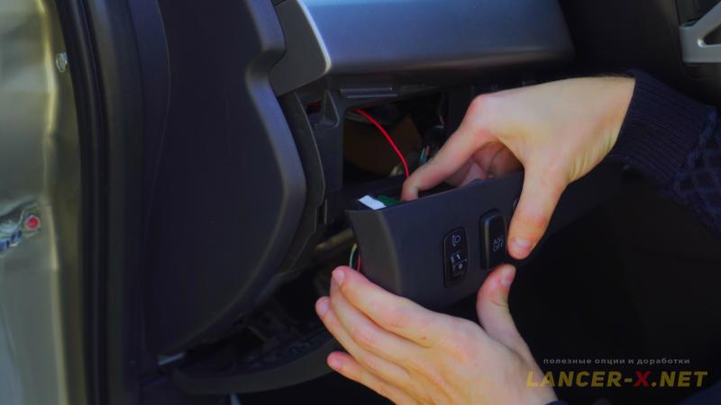 The wiring for button of electronic stability control system has restored.
Installation of G-sensor on Mitsubishi Lancer X
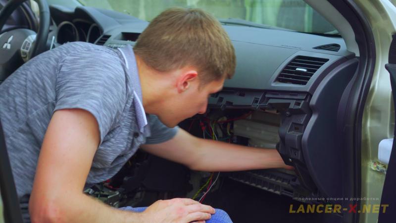
G-sensor is installed on the vehicle body in the very lower part under the dashboard.
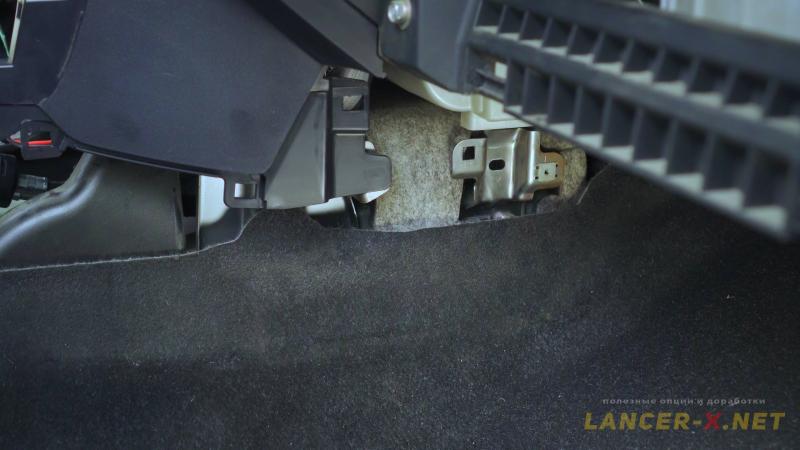 For its installation, it is necessary to disassemble the dashboard lower part, move the central tunnel and remove the lower side panels from the driver's and passenger's side.
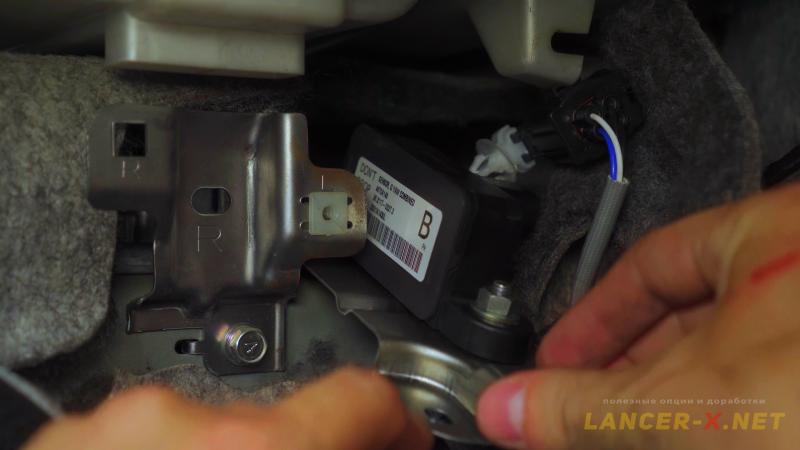 You will have the thread for the bracket installation from the factory, that is why fasten the g-sensor to the bracket, and screw the bracket to the vehicle body. The oxygen sensor will interfere with you, unlatch it from the body, screw the bracket, and fasten the sensor itself to the g-sensor bracket.
Next, it is necessary to lay wires up to hydraulic unit:
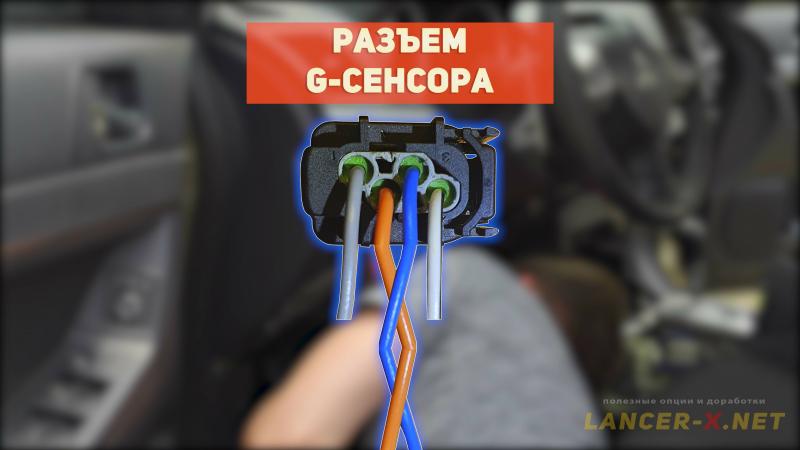 4 wires of 2 meters from g-sensor, blue and orange wires are the CAN bus bar, they must be obligatory spliced between each other throughout the length.
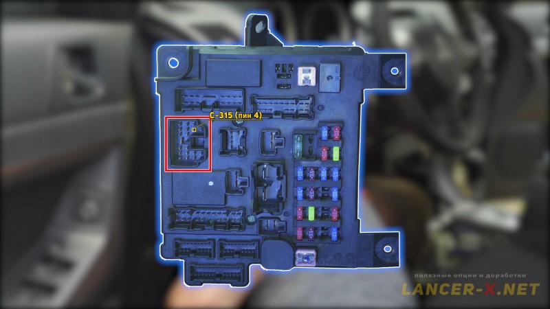 1 wire of 2,5 meters for the hydraulic unit supply from ETACS unit. On before restyling, one can take the supply from the c-128 connector pin 2. And on restyling, the c-128 connector is absent, that is why connect c-315 connector pin 4 directly to the ETACS unit.
But do not connect the wire of hydraulic unit supply, as in this case on this wire will be the voltage of 12 V. We will connect everything after installation of hydraulic unit three-row connector.
 I will lay these 5 Wires to the hydraulic unit through protective cover in the glove box. I remove it and make a hole of 5-6mm and then insert the wires.
  After that, I isolate the wires throughout the length and lay them to the hydraulic unit.
 I will lead these wires in the interior from the bottom up, in order to fully eliminate the water running-off in the interior from the underhood space.
 Installation of steering angle sensor on Mitsubishi Lancer X
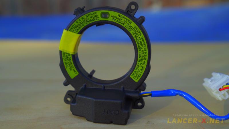
I have installed steering angle sensor 8651A084, I installed it in the article about Standard bi-xenon headlights and AFS system. But I remember how to install it.
 If you have before restyling Lancer X before 2011 year of manufacture, then the connector for steering angle sensor connection will be from the factory. And on restyled Lancer X, wiring and connector are absent, it is necessary to restore them.
To install the steering angle sensor 8651A084, it is necessary to disconnect terminals form the battery, remove dash panel and steering wheel.
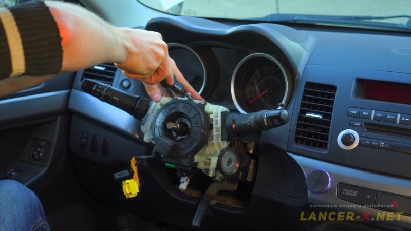 Be sure to make a mark on the steering wheel and steering wheel shaft to put the steering wheel back in the correct position.
Next, remove the base on which the levers for switching the turns and adjusting the operation of the wipers are located.
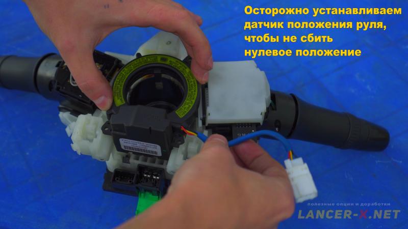 Carefully screw the steering position sensor onto it from the back side. The main thing is not to change the zero position. We lay the wires in a special groove.
And put everything back on the steering column.
There are 4 wires from the rudder position sensor, we connect them as follows:
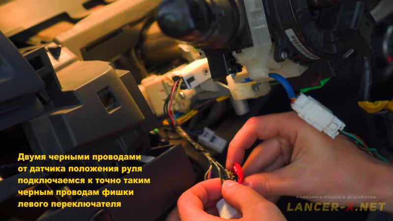 - With two black wires we connect to the same black wires at the left turn signal and light switch using compression terminals.
 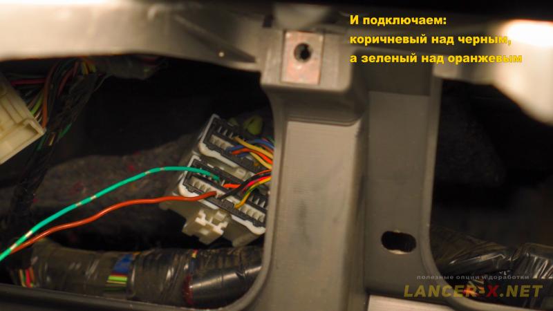 - The remaining 2 wires, brown and green, are pulled by the dashboard to two connectors. There will be a connector behind the dashboard, it is necessary to connect our remaining wires into it: brown above black, green above orange.
 Реклама. ООО "АЛИБАБА.КОМ (РУ)", ИНН 7703380158
That is all, the steering wheel position sensor is installed.
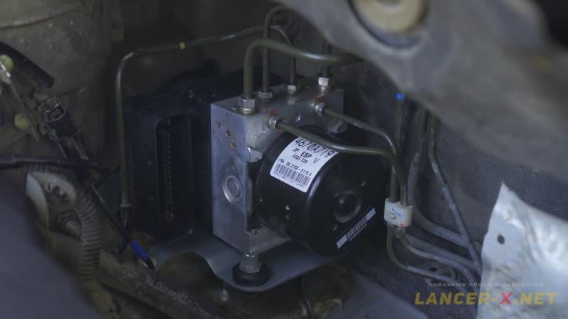
Installation of ABS/ASC 4670A719 unit on Mitsubishi Lancer X
Now we need to unscrew the bracket with old ABS unit and install the new ABS/ASC 4670A719 unit.
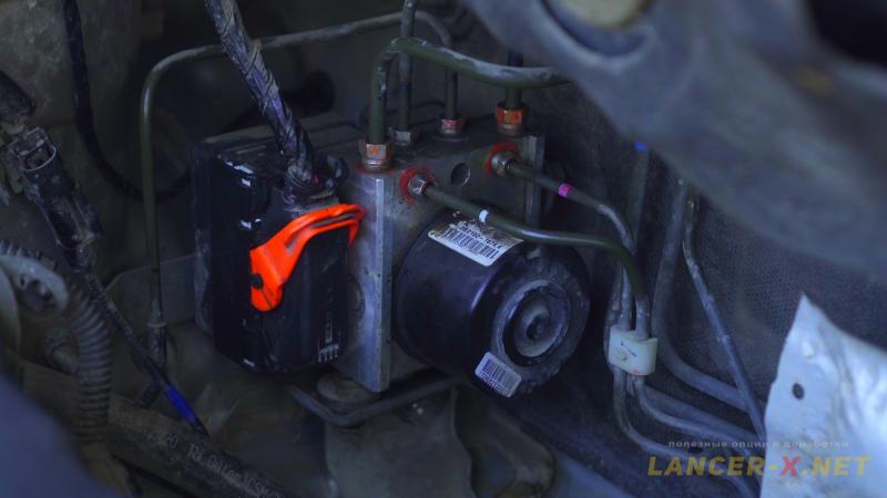 Remove two-row connector, for that purpose transmit simultaneously the orange fixator in the opening position and simultaneously remove it.
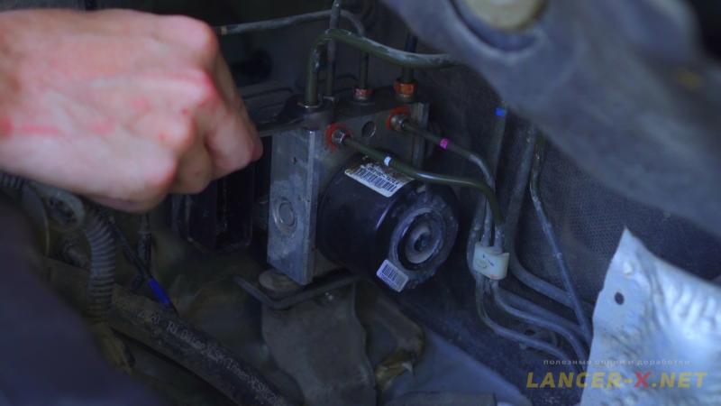 Next, it is necessary to unscrew 6 hydraulic tubes. Those, that are thicker, are input and unscrew with 12 mm wrench. Those, that are thinner, are output and unscrew with 10 mm wrench.
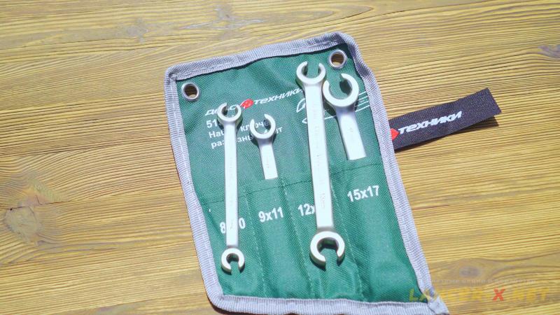 I used split keys. The input tubes were unscrewed with 12 mm wrench without any problems, but I could not unscrew the output tubes, given keys began to grind the edges.
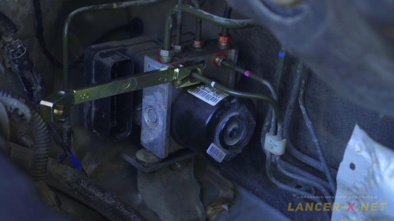 For this reason, I used upgraded wrenches with draw bolt. With the help of these wrenches, I unscrewed everything without any problems, keeping all edges on nuts.
 Unscrew the bracket, it is fastened with 3 nuts. Remove the old ABS unit and install the new one.
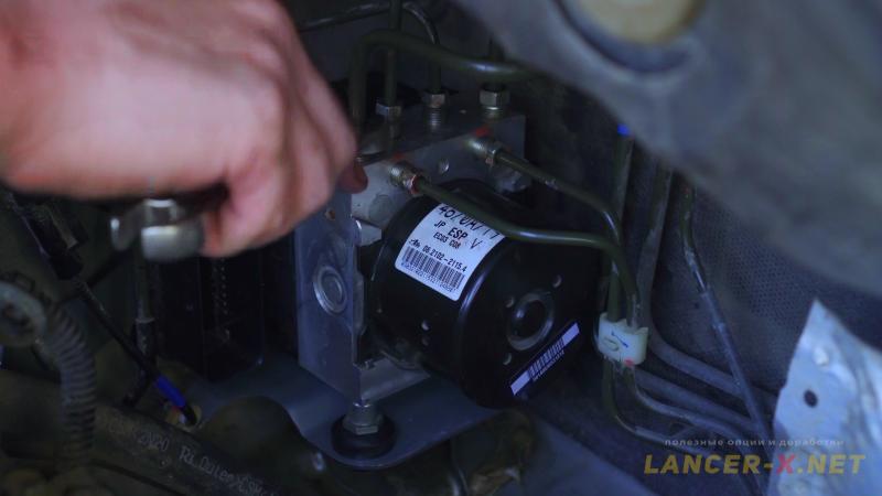 Screw, firstly, 2 input tubes to the new ABS/ASC 4670A719 unit and bleed the brakes a little in order to fill the unit with brake fluid. And only after that screw the remain 4 output tubes.
Repinning of three-row connector for ASC on Mitsubishi Lancer X
When you open two-row connector, you will see 15 wires. It is necessary to transfer these wires from two-row connector of ABS unit to three-row connector. And add 4 wires from g-sensor and 1 wire of hydraulic unit supply.
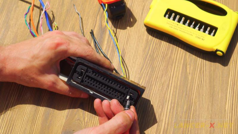 Disassemble connectors, remove upper cover, unlatch white pins fixator, the pins are held by small clamps, that are necessary to bend with a needle or thin driver, after that pins are removed without any problems.
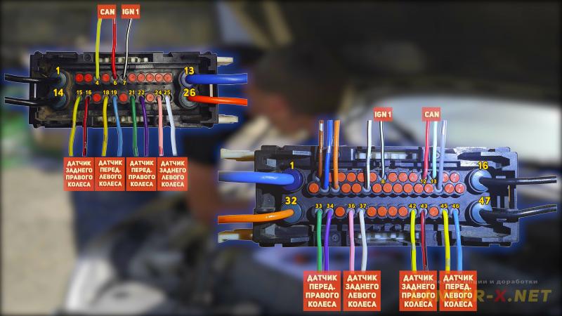 Transfer pins to three-row connector in accordance with the following scheme:
Pins 1 and 14 of two-row connector are the mass
- transfer pin 1 to the pin 47 and pin 14 to the pin 16.
Pins 13 and 26 of two-row connector are the supply of engine and valves in the unit
- transfer pin 13 to the pin 1 and pin 26 to the pin 32.
Pins 4 and 6 of two-row connector are the CAN bus bar
- transfer pin 4 to the pin 12 and pin 6 to the pin 13.
Pin 7 of two-row connector is the IGN 1 management
- transfer pin 7 to the pin 8.
Pin 15 and 16 of two-row connector are the rear right wheel sensor
- transfer pin 15 to the pin 42 and pin 16 to the pin 43.
Pins 18 and 19 of two-row connector are the front left wheel sensor
- transfer pin 18 to the pin 45 and pin 19 to the pin 46.
Pins 21 and 22 of two-row connector are the front right wheel sensor
- transfer pin 21 to the pin 33 and pin 22 to the pin 34.
Pins 24 and 25 of two-row connector are the rear left wheel sensor
- transfer pin 24 to the pin 36 and pin 25 to the pin 37.
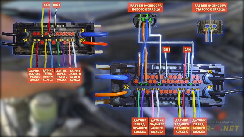 Next, add 4 wires from g-sensor to the three-row connector, as one has g-sensor of new type, then the connector is also of new type with 4 pins. I make the random numeration, the orienting point is the latch from the right.
Connect pin 1 of g-sensor to the pin 29 of three-row connector.
Connect pin 2 of g-sensor to the pin 19 of three-row connector.
Connect pin 3 of g-sensor to the pin 18 of three-row connector.
Connect pin 4 of g-sensor to the pin 22 of three-row connector.
Also, you can have g-sensor of old type, there will be 6-pined connector and the connection here is similar, orient by wires color.
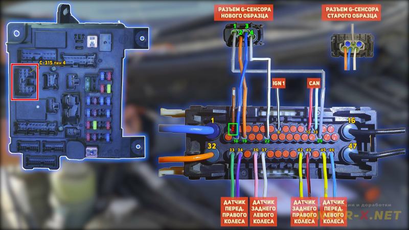 And connect the last wire to the three-row connector, the supply from ETACS unit from the c-315 connector pin 4 - connect to the pin 2 of three-row connector. And only now, one can connect this wire to the c-315 connector pin 4 of ETACS unit.
Latch the pins fixator, lay the wires carefully and connect the connector to the hydraulic unit.
After final installation of electronic stability control system, it is obligatory to bleed the brakes in accordance with standard scheme: bleed the rear right, then the front left, and next the rear left and front right.
 It is also obligatory to check the level of brake fluid in the tank, according to reducing - add the new.
Activating of electronic stability control system ACS (ESP) on Mitsubishi Lancer X
Before activating, I advise you to read the article where discussed in detail how to activate the hidden functions and options on Mitsubishi Lancer X.
For activating the electronic stability control system ASC/ESP on Lancer X, you will need:
1. J2534 compatible adapter. Bought here: Аliexpress
Реклама. ООО "АЛИБАБА.КОМ (РУ)", ИНН 7703380158
2. MMCodingWriter, the program for downloading and coding recording.
3. MUT Coding Mitsubishi, the program for coding editing.
4. Laptop.
Since 2021, the MUT Coding Mitsubishi program has become paid, or you can buy it from the developer, or use the built-in editor in the MMCoding Writer program.
Always do backup copies for original Variant and Custom codings!!!!!!!!!!
In the engine file (Engine ECU) activate:
- ASC - - > present
- ABS - - > not present
Find and activate the following points in the Variant:
- ABS - - > not present
- ASC - - > present
- SAS - - > present
- ASC - - > present
- SAS - - > present
- ESS turn lamp - - > present (If your unit support the ESS system)
- CHASSIS TYPE for ASC - - > Type 7 (someone could have Type 4 or Type 10).
If your ASC unit was removed from Lancer, then these codings are sufficient for activating. And if you install unit with ASX or Outlander XL, then except codings, mentioned above, you need to edit codings below. You need to set there the values, which were on the car from which your unit was removed.
Vhicle Line - - >
Transmission - - >
Engine Type - - >
Transmission - - >
Engine Type - - >
 Next ride on the even surface and calibrate in the MMCodingWriter program the g-sensor first, and then the steering angle sensor. That is all, the activating is completed.
I tested the electronic stability control system a little (ASC/ESP) on the gravel road, as well as HSA and ESS systems, everything operates perfectly. The installation is proved on 100 %.
Video instruction of electronic stability control system ASC installation on Mitsubishi Lancer X
Related links: