Useful information about Mitsubishi Lancer X
Load resistor for LED lamps
Power calculation of load resistor for LED lamps correct operation.

Lancer-X.net
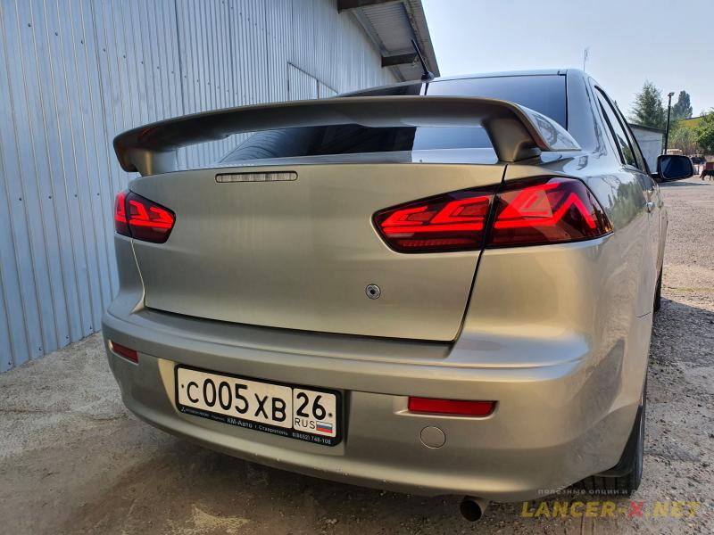
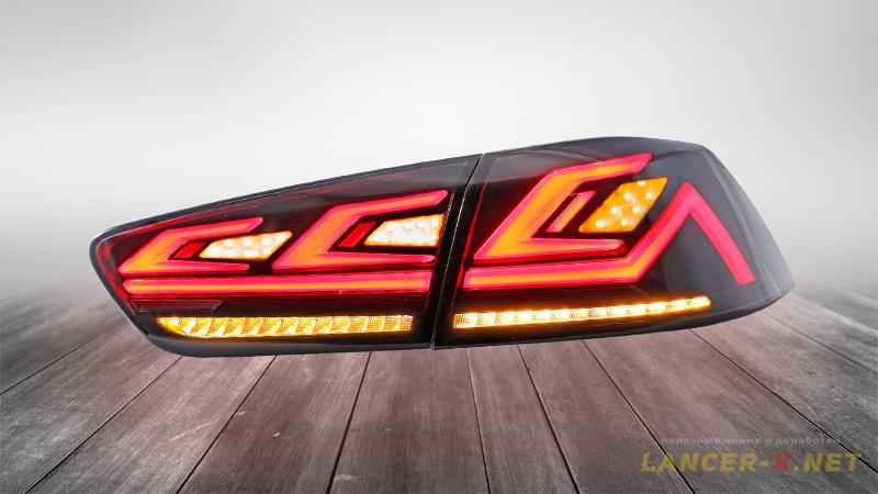
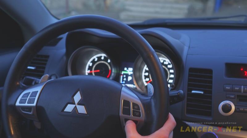
After installation of new fully LED rear lights on Lancer X, the cruise control stopped operating.
And the matter is that as these rear lights are fully LED, the car electronics thinks that supposedly the lamps in stop signals have burned and due to this the cruise control stops operating.
Also, the stability control system indicates the supposedly burned lamps in stop signals, reporting this with an error on the dash panel.
For easy reference, this instruction is represented in text and video format.
Why the error during LED lamps installation appears
The problem is common and exists on many other alternative optics. As well as when you install the LED lamps in standard rear lights (in stop or turn signals).
As LED lamps are more less in power than the filament lamps, a car thinks than supposedly lamp has burned in stop or turn signals and reporting the driver with the error about its change.
 The solution to the problem is easy, it is necessary to install the load resistor.
How to calculate the power, current and resistance of load resistor
There is the standard filament lamp in stop signals of 21 W on Mitsubishi Lancer X, as on many cars.
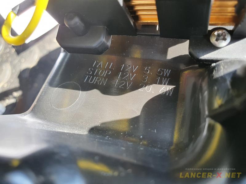 In new LED lights, the LED lamps of 8.1 W are installed.
Let us calculate the power of load resistor
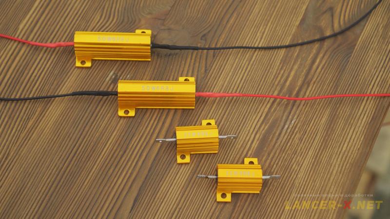
So, from 21W - 8.1W = ~13W, this is a necessary power of load resistor in order the error disappear on the car. But it is better to install more powerful resistor, for example for 25 or 50 W, as it will heat much less.
And if you install a LED lamp in turn signals, it is necessary to calculate the common power along left and right sides.
For example, the filament lamp of turn signals on the left side consumes 21 W and lamp in the fender 5W, lamps in rear lights 21 W. The common power is 21W + 5W + 21W = 47W.
And if you have decided to install the LED lamp of 12 W in the rear light, the common power along the left side in this case is 21W + 5W + 12W = 38W.
 And now from 47W - 38W = 9W is the necessary power of load resistor. But it is better to install more powerful resistor, for example for 25 or 50 W, as it will heat much less.
It is important to understand that, for example, when installing the resistor of 50 W, it is its power not per unit time, but maximum power quantity, which it can disperse. The more powerful resistor, the less it will heat.
Let us calculate the current of load resistor
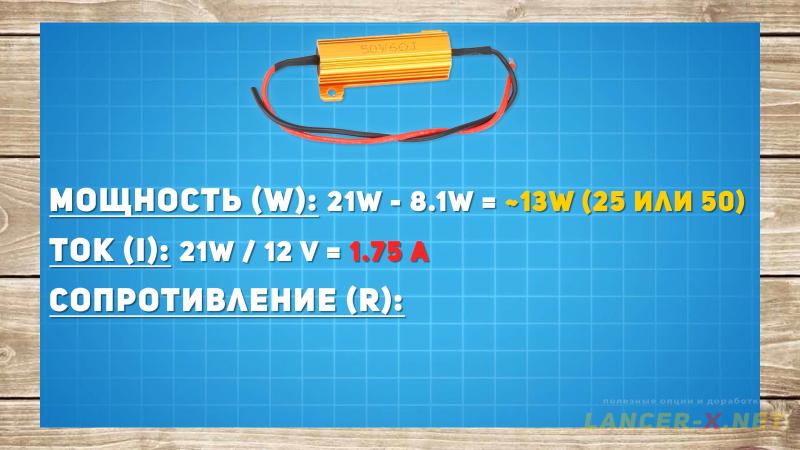 Next it is necessary to calculate the current, that must conduct through resistor. Divide the power of filament lamp by car network voltage: 21W / 12V = 1.75 A.
Let us calculate the resistance of load resistor
And now, using Ohm's law, we can calculate the resistance of load resistor, in order to do that divide the car network resistance by the current, which must conduct through load resistor: 12V / 1.75А = 6,86 Ohm.
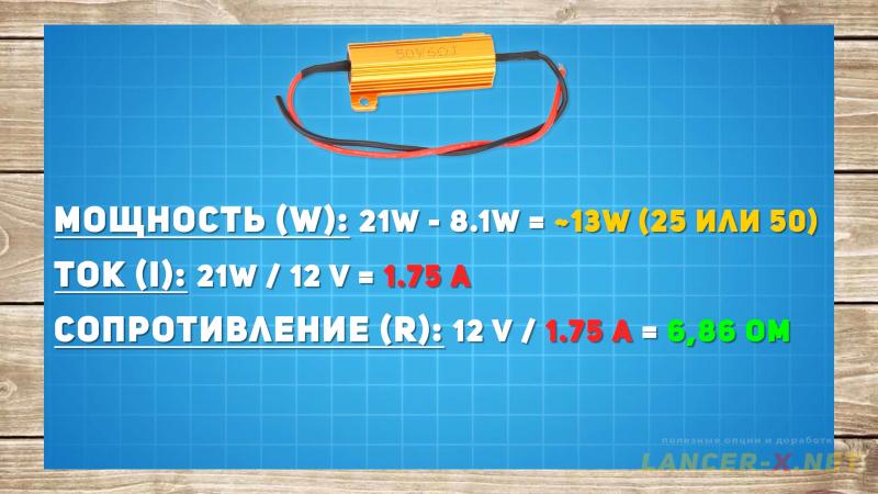
Thus, in order the car stops indicate the LED lamps error, it is necessary to connect the load resistor of 25 or 50 W with resistance of 6,86 Ohm.
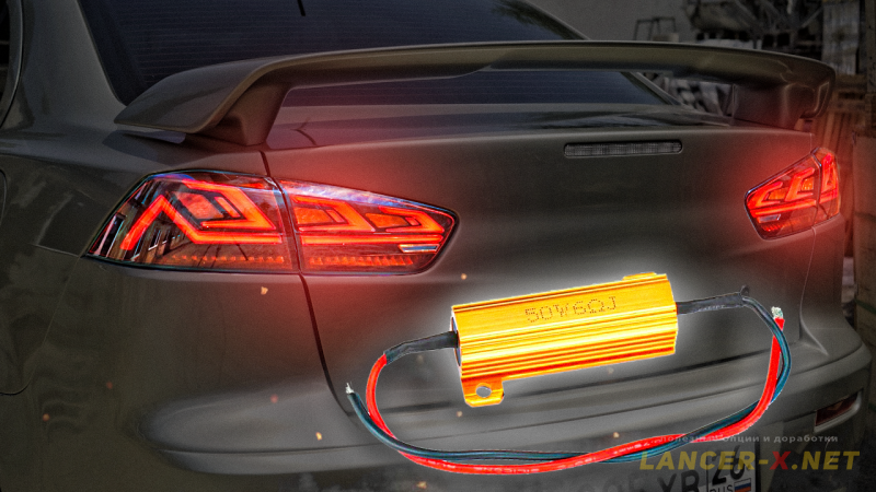
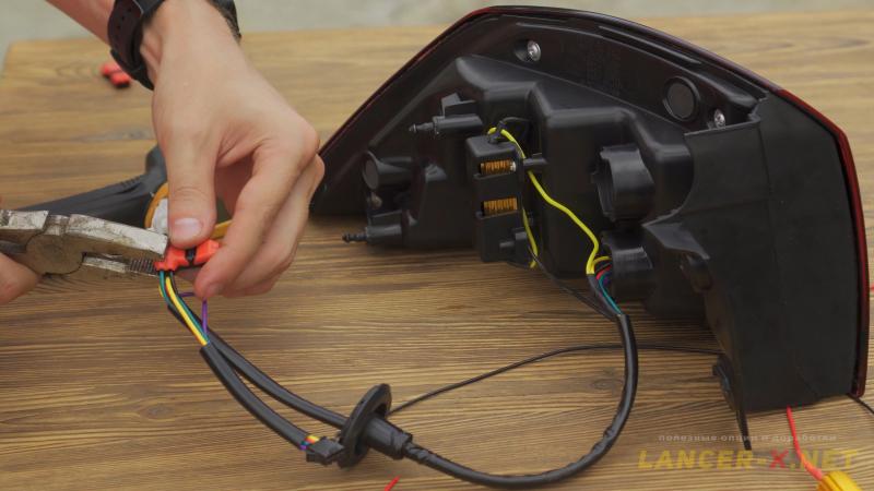 The load resistor is connected parallel to minus and plus of stop or turn signals. Resistor has not a polarity, one can connect it from either side.
I connected the load resistor of 50 W to the stop signals.
Реклама. ООО "АЛИБАБА.КОМ (РУ)", ИНН 7703380158
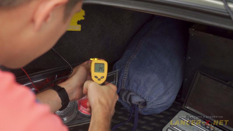 Next I have tested the stop signals with connected load resistors. Stop signals were continuously switched-on for 12 minutes, and as a result the resistors heated up to 34 degrees, that is a very good result. In principle, it is possible to install and for 25 W.
It is possible to fasten the load resistors on the double-sided adhesive tape or ties.
And if in your case they heat above 50 degrees, it is better to fasten them to the car's body using heat-carrying adhesive tape for heat removal.
Video of load resistor connection
[media=https://www.youtube.com/watch?v=3O3NZwQpC8I]
Related links: